Introduction
Mechanical advantage breathes life in a wide variety of machines and systems. The purpose of a machine is to convert one energy into another, this can be done with many mechanisms including levers and pulleys or even a car converting chemical energy into kinetic energy. Learning to convert one weak force into a stronger output has been at the heart of engineering since the development of the wheel. Creative uses of mechanical advantage have allowed us to develop some fantastic applications, and this article is going to show a few of these mechanisms!
We will focus on the design and benefits of systems with a variable mechanical advantage (VMA). VMA can get a bit more complicated than a standard mechanical advantage such as a lever or pulley, but it offers absolutely vital versatility to mechanical systems. A good example use case for VMA is a polishing/grinding application where a grinding wheel may have to move large distances to allow loading of material, and large forces when grinding. Rather than utilizing a constant gear ratio, a VMA can be used to move the grinding wheel into position quickly, then impart very high forces onto the specimen.
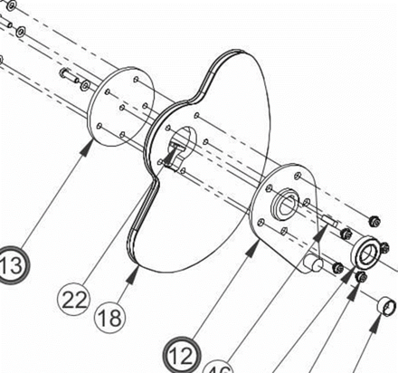
Large motion and Large force Eccentric Lever with ORCA™ motor
Unlocking VMA as a tool in a designer or engineers toolbox opens up some fantastic possibilities, and allows machines to achieve truly elegant results. If by the end of the report you’d like to discuss an application, get it touch with us here.
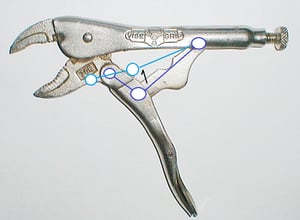
Introducing Variable Mechanical Advantage - Locking Pliers
What is VMA? When the advantage a system provides changes depending on the position of the system, this is called VMA. Locking Pliers are a fantastic first use case.

Locking pliers are incredible at converting grip force into a huge clamping force at the jaws of the pliers. Though what makes locking pliers different from standard pliers? The handle is squeezed just as much as ordinary pliers, the jaws close a similar distance, and the force applied to the handle isn’t that different between the pliers? The answer lies in Variable Mechanical Advantage. With careful attention paid to how the jaws move as the handle is closed, it can be seen that the jaws close swiftly at the start, then for the last few millimeters, the jaws close very slowly. This is an interesting phenomena caused by how the linkages of the pliers enable the mechanical advantage to increase as the jaws are closed.
Could really large pliers that have a huge lever arm be used to achieve the same force output? Yes, though those pliers would require a huge amount of space, and opening and closing the handle would be a full body exercise. Variable mechanical advantage allows effort to be concentrated exactly where it is needed.
The Math of Mechanical Advantage
As discussed in the introduction, mechanical systems just convert energy from one form into another, and calculating advantage ratios can be very straightforward. A 2:1 gear ratio multiplies the force by 2, and reduces the output distance by the same factor.

Though what happens when variable mechanical advantage is employed? Calculus happens! Observe the Force vs. Distance curve of the above example. The equation is essentially just calculus too. This is made clearer through the following drawings:
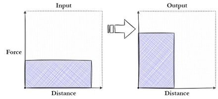
Plotting the input and the output of the system with force and distance, the integrals of the curves are the energies of the input and the output.

Using this, the following equation can be derived:

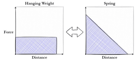
What the force distance curves of the locking pliers looks like if a constant force is applied to the handle:
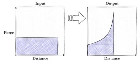
The area under both curves is the same, though with a variable advantage, effort can be concentrated to get much higher forces out of the system compared to standard pliers without increasing the size of the tool, while keeping a very reasonable distance.
Though this probably brings up the thought: “Neat, now how does one actually design a system with variable mechanical advantage?” A couple strategies will be discussed in the following section.
Designing Variable Mechanical Advantage
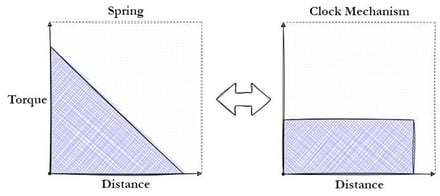
Designing the first clock mechanisms is a perfect example of how to design VMA. The original clocks were powered by hanging weights and slowly releasing that energy with the swinging pendulum. In the advent of miniaturization of clock mechanisms, better energy storage had to be invented. Springs are a much more mobile form of energy storage, and most watches today rely on springs to store energy. Though springs have an unfortunate drawback, their strength diminishes as they extend. The following figure shows what the Force distance curves look like for a hanging weight powering a clock versus the spring:
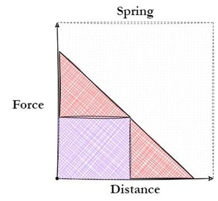
In certain machines, this issue doesn't pose a significant challenge. However, for clocks, it presented a significant obstacle that needed to be overcome. Clocks rely on a consistent torque to function properly, which is why the utilization of a hanging weight proved immensely valuable. Let’s say a clock requires the force output of the hanging weight to operate, if we directly power the system with the spring all of this energy will be lost:
The VMA system development begins by tackling two significant challenges. Firstly, when the spring is fully wound, it generates an excessive amount of energy leading to the production of heat and noise. Secondly, as the spring unwinds and reaches the halfway point, the clock would cease to function due to the system's requirement for a minimum torque to operate. These issues must be addressed to ensure the successful implementation of a VMA system, which leads to the first design tip:
Understanding load and supply
For this clock example, the original watchmakers wanted to power the system with a spring and get a constant output force:
Now that the input and the output of the system are known, dividing the output load by the input energy provides the required gear ratio of the system. The second step to developing a VMA is:
Determine the required gear ratio with respect to either the input or output distance
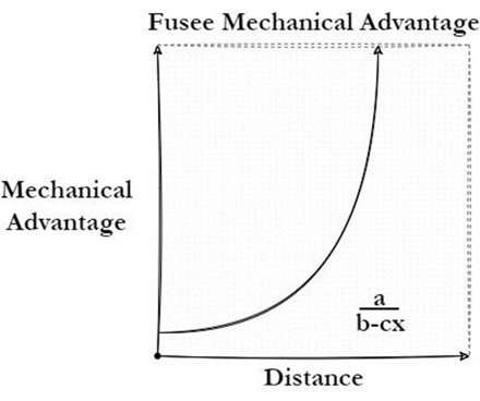
By knowing the gear ratio needed to utilize the spring, early watchmakers invented the Fusee. The fusee was essentially a pulley with a variable mechanical advantage that was used to linearize early spring power clocks. An illustration of a fusee can be seen below:
#/media/File:Lindquist_Fusee_Pocket_Watch_Movement.jpg)
https://en.wikipedia.org/wiki/Fusee_(horology)#/media/File:Lindquist_Fusee_Pocket_Watch_Movement.jpg
When the spring is wound up and has maximum force output, the fusee has the minimum gear ratio which essentially steps the force down. As the spring unwinds, the diameter of the fusee increases to allow the diminishing force of the spring to still power the system. The actual geometry of the fusee can get very complicated, since not only is the spring not completely linear in its output, the pulley design is not as simple as setting the diameter as a function of height, it needs to be a function of pulley arc length. Though for most use cases: close enough is good enough.
The fusee does not capture all available energy from the spring; the diameter of the pulley never gives a mechanical advantage much better than 1. This is due to diminishing returns on capturing the energy of the spring (Area under the force distance curve).
The final major step to developing a VMA is easier said than done:
Design a mechanical system that captures your required VMA
In the next section some mechanisms that can be used to achieve VMA will be outlined.
Types of Mechanisms for VMAs
1. Second Class Lever - Constant Moment
Interestingly, a huge number of naturally occurring mechanical systems feature VMAs. Human legs are a perfect example, and can be seen when leg pressing or squatting. Lifting weight with legs becomes significantly more difficult the more bent the legs are. In fact, this is exactly the same mechanism that provides locking pliers with their mechanical advantage. This is due to muscles providing a consistent moment on the femur and since the vertical load is offset from the pivot of the leg, the more bent the leg, the less linear force can be imparted with the same input moment. The mechanism is as follows:
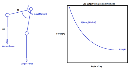
Note: This requires a constant moment applied on the lever. If that is applied by a linear force on the lever there is a constant mechanical advantage again. Looking at the locking pliers, the mechanism can be seen.
This mechanism benefits from the shape of the sinusoidal curve.As a lever rotates around a circle while trying to lift an object, at the top of the motion the lever rotates a large angle but only increases the height of the lever miniscule distances.
2. Eccentric Levers
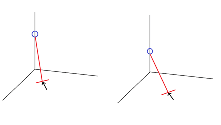
As discussed above, a typical lever converting one linear force into another never features a VMA. It might be counter-intuitive, but as a lever rotates the advantage ratio is always the same no matter how tilted the lever is, as long as the direction of the forces remains constant.
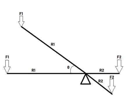
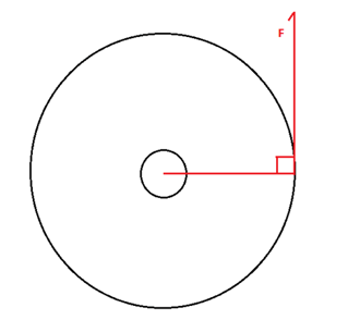
Horizontal Lever:

Tilted Lever:

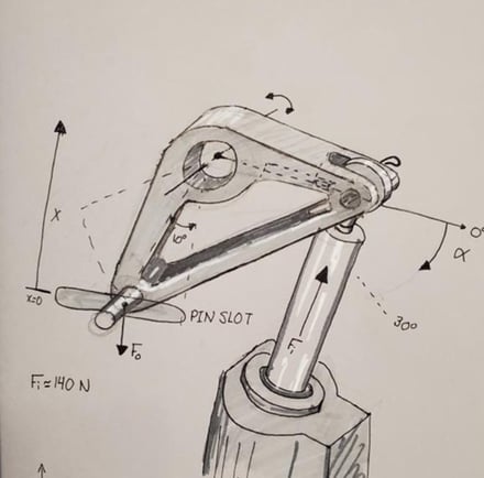
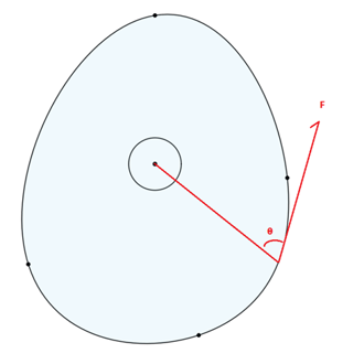
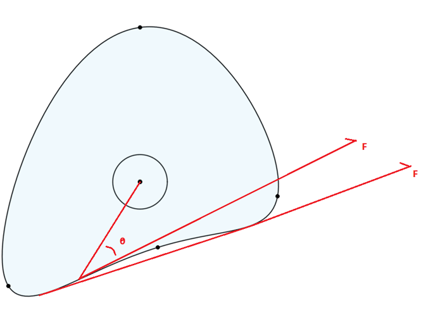
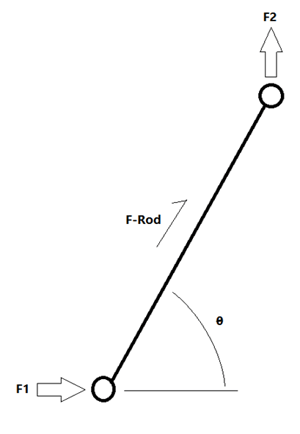
As the figure demonstrates, the gear ratio never changes. Though it requires a very simple change to a typical lever to add VMA. This is when the lever is no longer co-linear, rather the lever tilts at the fulcrum. This is the same mechanism as shown in the introduction.
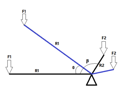
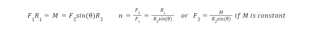
The value of such a simple change is how much versatility there is in adjusting the VMA. Deriving the gear ratio with theta starting when R1 is horizontal and rotating clockwise:

Where m is the ratio of the input to the output Lever lengths. An interactive Desmos plot that can be used to play with the variables and witness what kind of VMAs are possible is found here: Eccentric Levers.
A very powerful feature of this mechanism is that it is possible to emulate a linear VMA with it. The emulated VMA is not perfectly linear, though for most mechanical use cases it works just as well.
Another feature of this mechanism is the ability to apply very large loads with it, if β is set to 90 degrees the gear ratio of the system is phenomenal at the start.
3. Nautilus/Variable Pulleys
After discussing variable gear diameter, the next logical step is variable pulley diameter. The convenient aspect of these is that the arc lengths don’t need to remain equivalent, though that may cause some mechanical aliasing. The fusee is the variable diameter pulley that enabled springs to be used in pocket watches, and there are various use cases where this might be useful such as the custom pulleys found on workout equipment that linearizes force output. An example of a variable diameter pulley found on a leg extension workout equipment can be found below:
Some equations for a variable diameter pulley and a constant diameter pulley being driven by a constant moment are derived here:

This is for a constant diameter pulley, a variable diameter pulley has some factors that make the derivation a little more complicated:
To vary the diameter of a pulley, the force transmitted through the belt or rope is no longer constantly perpendicular with the instantaneous lever arm. The equation for the variable pulley is derived here:
An important note for variable diameter pulleys: Angular concavity can never be positive, this would result in the pulley interfering with the force transmission of locations before concavity shift.
Imagine a pulley with a positive concavity at some point around its circumference:
If the pulley rotates along this section, the driving rope would experience interference with the pulley itself. The above image shows that once the pulley rotates so far the driving rope would just sit on top of this divot and proceed with operation as if the pulley was a straight line through that segment. This is not a concern for variable diameter pulleys such as the fusee, where the pulley is not a continuous 2D form.
As can be seen, this topic is very extensive and versatile. Some introductory notes to this mechanism have been provided, and another article on the topic is planned in the future. An in-progress python script to design variable diameter pulleys for exact force profiles will be included in the follow up article.
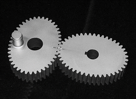
4. Variable Gear Diameter/Nautilus Gears
The nautilus gear design is a fantastic 3D printable demonstration of VMA. A photo of one of these gear sets can be found below:

The typical advantage ratio of a gear train is as follows:

Where 𝞽 are the torques of the respective gears, and R is the Radius of said gear. Most gear systems keep the gears at a constant distance, this is the only scenario that is considered here. Therefore, the sum of the radii must be constant. With a constant gear diameter, this is always true. The nautilus gear shown above varies the radii of the input and output gears as a function of angle, shown below as n being a function of the angle.

A very important note about these gear sets: The arc length (circumference) of the gears must be equivalent! If the arc lengths are different, the gear set would work for one rotation, then fall out of phase and jam. In general, it is significantly easier designing a gear with a continuous profile as opposed to the discontinuous profile of the nautilus gear above, the remeshing of the gears at the point of discontinuity is a failure point, the contact stress is focused on one gear tooth. Elliptical gears are a perfect example of a continuously variable gear ratio.
In order for the arc lengths of both gears to match up, the average gear ratio of variable gears is 1. Combining this gear set in series with a gear set with a constant gear ratio allows the gear train to multiply forces with a VMA.
5. Scott Russel Mechanism / Pushrod
A mechanism that has been found to be incredibly powerful when paired with Iris Dynamics linear motors is the Scott Russel Mechanism, or equivalent using pushrods. ORCA Series linear motors sometimes require the output direction to be different from the orientation of the motor, while solving this problem the versatility of using the Scott Russel mechanism to convert direction of motor input while also allowing VMA as well was discovered. An example of this mechanism can be found below:
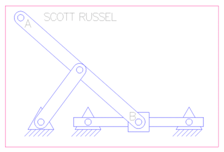
As the input B moves horizontally, output A moves vertically. In this case, the second linkage serves as a replacement for a linear bearing on A. As the input moves through its path, the relative angle of the connecting rod and the input changes, also changing the mechanical advantage. A method to describe the mechanical advantage is as follows:
Imagine pushing a bowling ball up the corner of a room using a broom resting into the same corner under the bowling ball, somehow perfectly balancing. Would it be easier to lift the bowling ball when the broom is at 45 degrees? Or at 60 degrees?
Intuitively, it gets easier and easier to lift the bowling ball the steeper the broom is. Now time for the derivation:

The advantage formula of this mechanism is very straightforward. Be mindful both points require assistance either from linear bearings or an additional linkage as seen in the Scott Russel mechanism. Another Desmos plot that seeks to determine operation regions of this mechanism dependent upon the average mechanical advantage and the output travel distance can be found here: Push Rod Mechanical Advantage.
It is also possible to vary the relative angles of this mechanism, if the angle between the forces is β:

Another boon of this mechanism, especially for Iris Dynamics’ purposes, is connecting two of these mechanisms to the same output. This allows 2-DoF control of the output without additional bearings, while allowing fine tuning of the loads in the operating region. However, that is a topic well deserving of its own paper.
Conclusion
We have thoroughly explored the versatility of Variable Mechanical Advantage (VMA); delving into its historical significance, particularly in the development of spring-powered pocket watches utilizing the Fusee mechanism. Additionally, we have examined a few mechanisms that exemplify the concept of VMA.
While this has only scratched the surface of this topic, this article serves as a valuable starting point for those interested in designing with VMA or recognizing its impact on systems, whether intentional or accidental. Whether you're designing new mechanisms or analyzing existing systems, this knowledge will prove instrumental.
If you found this article useful, connect with me on LinkedIn and let me know! And if you find other useful mechanisms that feature VMA, please share!