.png?width=1100&height=619&name=Blog%20Banner%20for%20Website%20Content%20(2).png)
June 19, 2024
For engineers, choosing components that meet application requirements while keeping costs and complexity low is crucial. This is especially important when selecting how to power a linear electric motor. Choosing the wrong power supply unit (PSU) could limit the performance of a linear electromagnetic motor and increase expenses. In this article, explore how PSU selection can affect linear actuators and learn how to optimize voltage and power ratings to save costs and simplify design. This article discusses Iris Dynamics’ line of DC electric tubular motors known as the ORCA™ Series Smart Linear Motors, which, like other electric actuators, can be affected by the PSU Voltage and Current/Power ratings.

.png?width=1100&height=163&name=Title%20(3).png)
How are PSUs selected for linear actuators?
- Use whatever PSU is already on hand, or
- Source a PSU that guarantees full performance from the motor, or
- Calculate the PSU minimum requirements and sourcing an optimal PSU by
a. Locating the application’s critical forces and speeds on the datasheet plots, or
b. Using the application’s critical forces and speeds in the formulae included in this guide.
Where to Start
When Detailed Application Requirements are Unknown
Often the required force and/or speed information required to select an optimal PSU will not be precisely known ahead of time. In these applications, it’s a good idea to select a supply that enables the maximum performance of the motor, knowing that this may increase the size and cost for the initial test setup.
- Data Logging: Once the motor(s) are in operation, their data logging capabilities can be used to capture the application’s requirements in terms of force and speed. This data can then be used to determine an ideal power supply voltage and power rating.
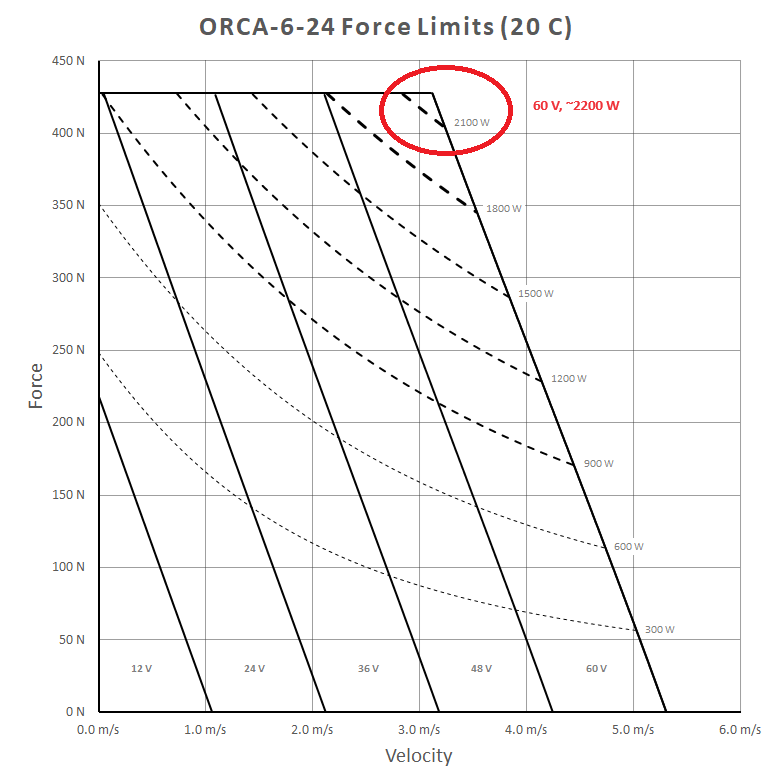
- Maximum-Capacity: Usually a list of so-called ‘maximum-capability’ power supplies will be available in the motor’s documentation. To determine such a supply based on the datasheet plots, find the point on the force vs speed plot which is the furthest up the y-axis (Force) and furthest right on the x-axis (Speed). This will indicate the voltage and power requirements.
For example, from the following plot of an ORCA-6-24V, one can see that about 2200 W and 60V is the most amount of Voltage and Power the motor might require, which would achieve around 425 N at about 3.2 m/s.
As a quick reference, below is a list of PSU ratings for each of Iris Dynamics’ ORCA motors that fully enable the functionality of that motor:
Table 1: Maximum PSU Requirements
| ORCA-6-LITE | ORCA-6-24V | ORCA-6-48V | ORCA-15-48V |
| 30 V, 500 W | 60 V, 2200 W | 60 V, 2200 W | 60 V, 2200 W |
Again, note that most applications will not require these ratings. Often lower voltages and lower power ratings will satisfy the application’s requirements and will also reduce the cost and size of the PSU. Further in the article we explain how to reduce these ratings.
When Detailed Application Involves Very Low or No Speed
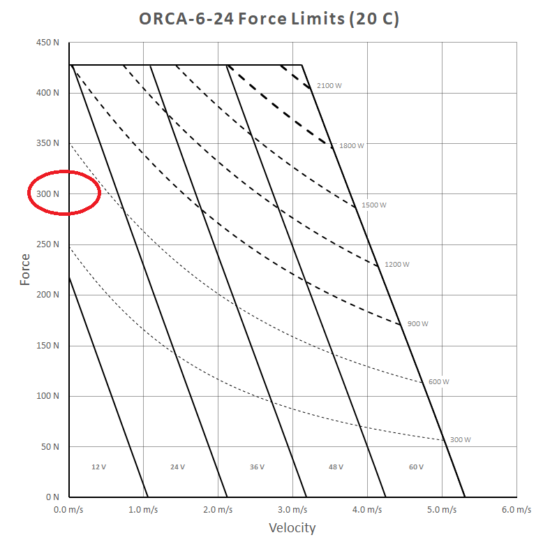
In these applications, the task of selecting a PSU is much simpler. The minimum voltage and power can be found by checking the force vs speed plot along the y-axis (where speed is zero). Locate the required force on the y-axis and find the voltage and power curves that exceed this point. These are all valid voltage and power ratings for the PSU.
For example, again looking at the ORCA-6-24V at 20 C, if an application requires a force of say, 300 N, we find that a PSU of 24 V and ~500 W meets that requirement.
Alternatively, the following equations could be used to find a more precise answer:
 Equation 1
![]() Equation 2
Equation 2
- P is PSU power rating in units of Watts
- V is PSU voltage rating in Volts
- F is motor Force output in units of Newtons
- K1 and k2 depend on the motor model and are found at the end of this section.
When the Application Requires Fast Motion, Large Moves or Vibration
Once motion is introduced, the considerations for the power supply begin to become more complicated. As any high speed electric linear actuator moves, it generates back electromotive force (EMF) voltages which must be overcome resulting in an increased voltage. As speed increases at a given force, the motor transfers more mechanical power to its load, demanding more power from the power supply. Practically, this means engineers need to know the forces required at each speed in their application to ensure their power supply has enough voltage and current.
Finding Required Voltage
The required voltage for each ORCA motor’s force and speed can be found by checking the motor’s force vs.speed plots in the datasheets, or by using this equation:
 Equation 3
![]() Equation 4
Equation 4
- P is PSU power rating in units of Watts
- V is PSU voltage rating in Volts
- F is motor Force output in units of Newtons
- k1 through k4 depend on the motor model and can be found below
Table 2: Equation Constant Values for Common ORCA Series Models
| at 25 C | ORCA-6-LITE | ORCA-6-24V | ORCA-6-48V | ORCA-15-48V |
| k1 | 1.88E+02 | 2.02E+02 | 2.02E+02 | 5.04E+02 |
| k2 | 8.18E-02 | 5.59E-02 | 8.41E-02 | 5.60E-02 |
| k3 | 6.70E-03 | 3.13E-03 | 7.07E-03 | 3.13E-03 |
| k4 | 1.02E-04 | 8.42E-05 | 8.41E-05 | 4.79E-05 |
| at 70 C | ORCA-6-LITE | ORCA-6-24V | ORCA-6-48V | ORCA-15-48V |
| k1 | 1.59E+02 | 1.71E+02 | 1.71E+02 | 4.27E+02 |
| k2 | 9.67E-02 | 6.61E-02 | 9.93E-02 | 6.62E-02 |
| k3 | 9.35E-03 | 4.37E-03 | 9.87E-03 | 4.38E-03 |
| k4 | 1.02E-04 | 8.42E-05 | 8.41E-05 | 4.79E-05 |
How to Refine
Smart motors, like ORCA motors, capture and provide a lot of information. This data is valuable for engineers during prototyping and commissioning, as it helps validate PSU selection, find ways to reduce costs and identify unmet application requirements.
Let 'er Rip
Once an ORCA motor is installed and performs the desired function in the system, it’s often a good idea to capture and analyze the data. Particularly the forces, speeds, temperature, and voltage can be streamed from the motor to a logfile during operation.
Analyzing Performance
This logfile can be analyzed to determine the peak power and voltage needs, and to capture the forces and speeds at varying times.
How to Reduce BOM Cost
By applying the above applications and captured forces and speeds, the maximum required voltage and power can be calculated, resulting in smaller and less expensive power supplies!
Common Problems with PSUs
1. Voltage is Below Minimum Operating Voltage
If the voltage falls below the minimum operating voltage the motor may not start or may only power its logic system and display an error.
2. Voltage is Above Maximum Operating Voltage
For ORCA motors, if the supplied voltage exceeds the motor’s maximum, it may display an error or draw significant current. A fast-blow fuse usually prevents damage, but without one or with an incorrectly sized fuse the motor may fail, likely shorting out.
3. Reverse or AC Voltage is Applied
ORCA motors short out when reverse voltage is applied, but a correctly sized fast-blow fuse can help to prevent damage. However, without a properly specced fuse this could result in the death of the motor.
4. Current / Power Rating is Too Low
When an application demands the motor to exert more force or mechanical power than a supply can provide, a few symptoms may present themselves. Adjustable lab supplies can commonly emit some sort of buzzing or clicking sounds as they rapidly enter and exit overcurrent protection. Another common symptom is for the voltage to drop. When it falls below the motor’s minimum operating voltage, the motor will throw an error and become compliant. Supplies with self-resetting overcurrent protection tend to buzz when the motor draws enough power, while those with latching protection often cut their power causing the motor to become compliant.
5. Voltage is Too Low
The supply voltage limits the force a motor can apply, and this becomes more of a problem as speed increases. When the voltage is too low, the required static forces might not be achieved, or motions may be slower than programmed.
6. Regenerative Power Cannot be Absorbed
Although power regeneration isn’t discussed in this article it’s important to note that some PSUs may activate a protection mode if the motor begins to generate enough power. If a supply can’t absorb energy during braking, its output voltage will climb, which may cause the PSU to enter over-voltage protection mode. The responses will vary, some supplies may briefly shut down with a ‘clicking’ sound before resuming normal operations. Others may require power removal and reapplication to reset. Adding external capacitors to the supply output can help mitigate this issue by absorbing excess energy from motor braking and preventing voltage spikes that trigger protection.
