- October 3, 2023
How fast is an ORCA™: Max Speed explained
In motion control applications, the maximum speeds of linear actuators are often a critical design parameter and often totally rule out some products as potential solutions. An actuator's maximum speed depends on the technology used: ballscrew, belt, pneumatic, hydraulic, linear motor, etc. Within these technologies are a number of important design factors that influence how fast it can get moving. This article looks at what limits the ORCA Series linear motor's maximum speed, and discusses how to interpret the max speed plots provided by Iris Dynamics.

The ORCA-6-LITE
What set's the speed limit?
Tubular linear motors like the ORCA Series are very mechanically simple: the shaft slides back and forth guided by bushings. These motors have no mechanical gearing and very low friction so the maximum speed is only limited by the motor's ability to generate forces. The motor does this by creating magnetic fields which push or pull on the shaft's fields.
When the motor is motionless, it can ramp up to max force in either direction almost instantly - typically within about 2 milliseconds. However, as the shaft starts to move relative to the motor body, something happens that tries to slow things down. That something is often called "Counter Electromagnetic Force" or Back Electromotive Force (Back-EMF), and is a natural consequence of our universe. It's this phenomena that dominates the motor's ability to achieve higher speeds, and the way the motor fights against it is with its supply voltage.
The amount of Back EMF that a motor produces is the consequence of a number of factors such as shaft construction, physical geometries, and winding configurations. Iris Dynamics offers different winding configurations within its lineup of linear motors.
Supply Voltage
The Back Electromotive Force shows up in the motor as a voltage in the windings. This voltage acts to create currents which would in turn generate magnetic fields that create braking forces that would slow the motor down - unless the motor applies additional voltage to the windings to offset that Back EMF voltage.
At rest, the motor applies the supply voltage to generate the magnetic fields that create force and consequently motion; as the motion increases, it must use additional voltage to offset the Back EMF. As the motion increases, so does the voltage required to overcome Back EMF and prevent braking.
It is this relationship that ultimately limits the motor's speed: at some point, the amount of Back EMF will be equal to the available supply voltage. At this point (which is sometimes called the unloaded max speed), the motor can only overcome the Back EMF, and there is no voltage remaining to generate forward force or accelerate further.
The takeaway here is that speed is influenced by voltage and increasing supply voltage increases the maximum speed.
Which Winding?
The way that a motor is wound internally plays a part in the maximum speed of the motor. For example, consider the ORCA-6-24V and ORCA-6-48V motors. Both motors use the same shafts, and both are the same size with the same amount of copper, but one has a higher maximum speed than that other.
While both contain the same number of copper windings, the difference lays in how they're connected. The ORCA-6-24V uses more parallel connections than the ORCA-6-48V and the result is that it generates less Back EMF. The tradeoff is a bit nuanced, but ultimately comes down to the fact that the ORCA-6-24V has a lower peak force output than the ORCA-6-48V does, but instead has a higher maximum speed. This is the only real difference between the motors, so when hitting the highest possible speed is the goal, the ORCA-6-24V is the right choice.
How to read ORCA Series speed limits

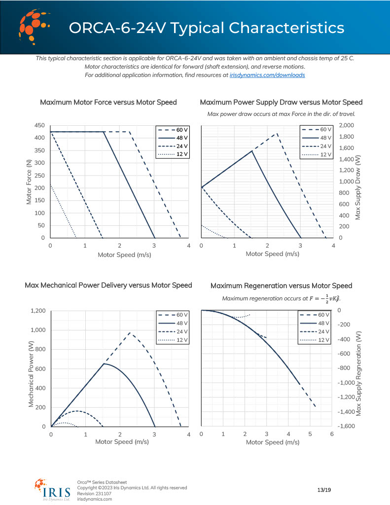
Speed Characteristics of the ORCA-6-24V from the ORCA Series Datasheet
The ORCA Series datasheet lists each motor's behaviour at common supply voltages.
Maximum Force vs Speed
This plot shows the relationship between increasing speed and decreasing maximum force. Any force under the limit lines are achievable at a given voltage.
The horizontal sections of the lines for some motors like the ORCA-6-24V are due to driver current limits. At these speeds and supply voltages where the lines appear flat, the motor has sufficient supply voltage to both overcome the back EMF while still maintaining the maximum rated force output. When the lines later slope downward, there is no longer sufficient voltage to both overcome back EMF while maintaining the full force output, and as a result the maximum force output falls.
The speed at which the maximum force output is zero is considered the maximum speed at that voltage.
Maximum Power Supply Draw vs Speed
This is an important plot to consider when sizing a power supply for an application if high speeds and forces are expected. Looking at the ORCA-6-24V, it can be seen that the motor can draw up to 900 W when at rest. However, if the motor is to continue to output the 425 N as the speed increases, the motor will draw more and more power, as seen in the plot.
In general, the power drawn by the motor is calculated by adding the power burned as heat by the motor with the mechanical power delivered. The power burned as heat is equal to [force output * force constant ]^2. The mechanical power delivered is equal to the [force output * speed].
Max Mechanical Power vs Speed
When a certain amount of mechanical power (force * speed) is known, this plot can be a good resource to determine if a motor is capable, and if so, at what voltage it must be powered.
Maximum Regeneration vs Speed
In situations, the Back EMF from the motor can exceed the voltage required to power the motor. When this happens, the extra voltage is fed back into the motor's power source and the motor begins to generate power. This last table can be used as a worst-case (or best-case depending on perspective) for power regeneration. In some cases - specifically with certain AC-DC or DC-DC switching power supplies, this backwards power is not well received and can trigger the protection functionality of the power supply, shutting it off.
