
How Thermal Capacity, Duty Cycle, and Cooling Determine Sustained Force Capabilities
A motor's ability to sustain force depends on its heat generation, thermal capacity, and cooling conditions. This paper uses a water-tank analogy to explain how these factors, together with duty cycle and ambient temperature, determine thermal performance.
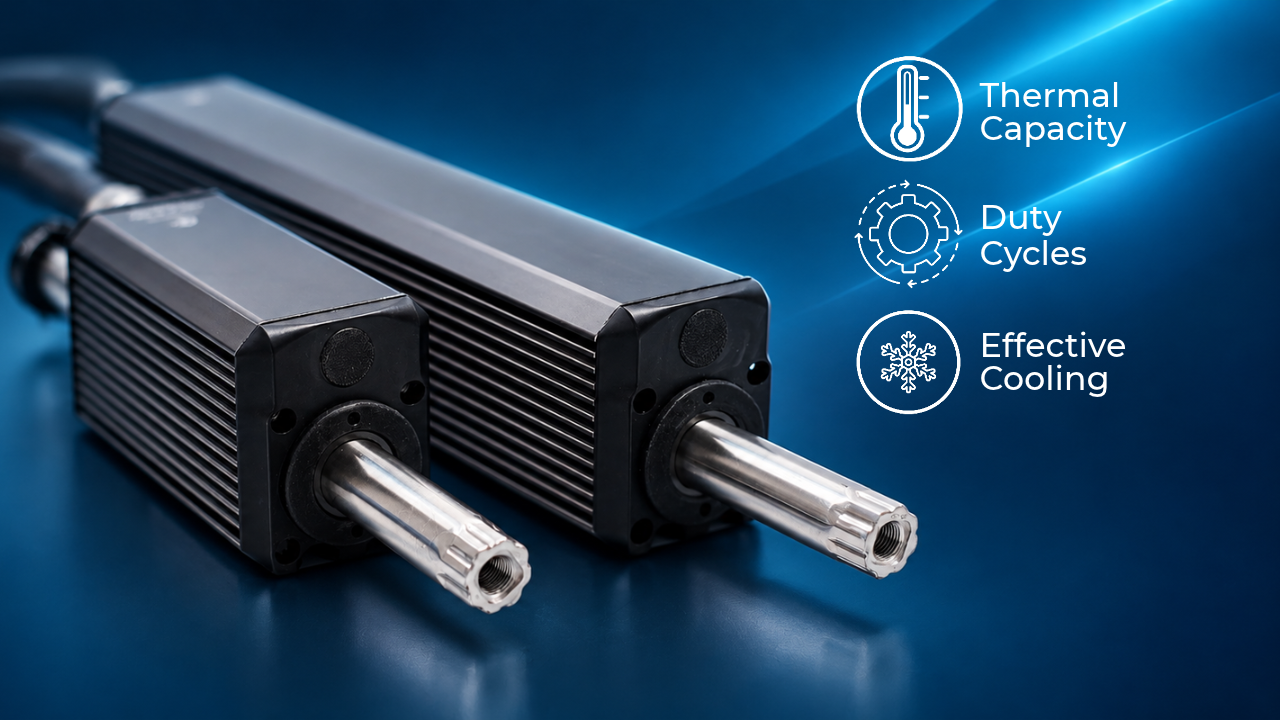
A comparison of the ORCA-6-24V and ORCA-12-12V supporting a 25 lb load illustrates why motors with identical maximum force ratings can have different continuous operation capabilities.
Definitions
| Maximum Force | The highest force a motor can produce under specified electrical and operating conditions. The duration for which this force is available depends on the motor’s initial temperature, heat generation, cooling, and thermal limits. |
| Continuous Force | The highest force a motor can sustain without exceeding its thermal limits under specified ambient temperature, mounting, and cooling conditions. |
| Thermal Capacity | The amount of thermal energy required to increase the motor’s temperature by one degree, measured in joules per degree Celsius (J/°C). A greater thermal capacity allows a motor to absorb more energy for the same temperature rise. |
| Duty Cycle | The percentage of a repeating cycle spent performing the loaded task, including any time spent holding the load. For example, holding a weight for 5 seconds and resting for 15 seconds gives a duty cycle of 25%. The rest period must reduce the force demand to reduce winding heating. Remaining stationary while supporting the same weight still counts as loaded time. |
| Direct Drive | A motor configuration in which electromagnetic force acts on the load without an intervening mechanical transmission. In an ORCA™ motor, current must continue flowing to maintain a holding force, even when the shaft is stationary. |
The Difference Between Maximum Force and Continuous Force
Maximum force describes a motor’s available force output under specified conditions. Continuous force describes the output it can sustain while remaining within its thermal limits.
At a continuous operating point, the motor transfers heat to its surroundings as quickly as it generates it. Higher forces increase winding heating and may cause thermal energy to accumulate. The motor’s thermal capacity allows it to absorb this additional energy temporarily, but operation must change before its temperature limit is reached.
Motor selection therefore requires more than a maximum force rating. It must also account for how long the force is applied and how frequently the task repeats.
Thermal Model of a Motor
A motor’s thermal behaviour depends on the balance between heat generation and heat removal. Electrical losses generate heat within the motor, while heat transfer to the surroundings removes it. The difference determines whether the motor warms up, cools down, or maintains a stable temperature.
The Water Tank Analogy
| Water-Tank Feature | Motor Equivalent |
| Incoming Water | Heat generated within the motor |
| Outgoing Water | Heat transferred to the surroundings |
| Water Level | Motor temperature |
| Tank Capacity | Capacity to adsorb thermal energy before reaching the temperature limit |
| Overflow Level | Motor temperature limit |
When water enters faster than it leaves, the level rises. Likewise, a motor’s temperature rises when heat generation exceeds heat removal. Continuous operation is possible when these rates reach equilibrium below the temperature limit.
Heat Generation: Filling the Tank
The motor produces force by passing current through its windings. Winding resistance converts part of the electrical input into heat:

 reflects electrical power,
 is winding current, and
 is winding resistance. Force is approximately proportional to current. For a fixed winding resistance, doubling the force therefore produces approximately four times the winding heating. ORCA motors have published force constants to determine the electrical loss when outputting a force:
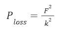
Where  is force, in newtons (N), and
 is the motor constant used in this relationship, in
 A higher motor constant means you get more force for every watt of heat lost in the windings.
In the tank analogy, increasing force opens the inlet further. Holding stationary load also keeps the inlet open because current must continue flowing to maintain the holding force.
Mechanical Power
During movement, electrical input supplies both mechanical power and motor losses. The overall power draw from the power supply can be seen below:
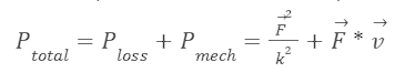
Where  is velocity along the force axis, and only the
 contributes to increasing the temperature of the motor.
Mechanical power is positive when force acts in the direction of motion. When force opposes motion, mechanical power is negative and the motor absorbs energy from the load. For motion in multiple dimensions, mechanical power is expressed as the dot product of force and velocity.
Within this simplified thermal model, the loss term represents the heat generated in the windings. Mechanical power transferred to the load is treated separately.
Force Constant and Temperature Relationship
The force constant of a motor is not consistent across all temperatures. The force constant is a simplification of the magnetic fields and winding resistances of a motor. As a motor heats up, its force constant decreases. Utilize the following equation to determine the new force constant from the room temperature constant:

Where T2 is the temperature of the coils. The datasheet has this value posted for 70°C. See example calculation below using an ORCA-6-48V:

Duty Cycle
Often, the most effective method to reduce incoming thermal power is to allow the motor to rest. A duty cycle is calculated with the following equation:
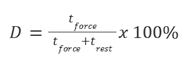
Where is the duty cycle in %,
 is the length of time force is being applied for and
 is the time the motor is at rest for.
Thermal Capacity: The Size of the Tank
Thermal capacity determines how much energy the motor can absorb for a given temperature rise. It depends on the mass and specific heat capacity of its materials, including the windings, stator, and housing.
A motor with greater thermal capacity corresponds to a larger tank. For the same initial temperature and net heat input, it takes longer to reach its temperature limit.
Greater thermal capacity therefore extends the duration of temporary overloads. Continuous operation still requires sufficient heat removal.
Heat Removal: Emptying the Tank
Heat travels from the windings through the motor’s structure and leaves through convection to the surrounding air, conduction into mounting structures, and thermal radiation.
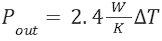
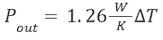
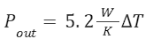
As the motor becomes warmer than its surroundings, heat removal increases. In the tank analogy, a higher water level increases the outlet flow. The level stabilizes when outgoing flow matches incoming flow. The equation for power out is as follows:
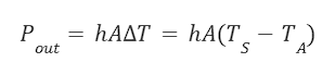
Where  is the convective heat transfer coefficient in W/m2K,
 is the contact area for the cooling medium, and
 is the difference in temperature between a stator
 and its surroundings

The calculation to determine the appropriate  and
 values is convoluted, instead the ORCA motors datasheet includes the following quick reference information:
|
Motor |
Passive Cooling |
Forced-Air Cooling |
|
ORCA-3 |
18 W |
Approximately 60 W |
|
ORCA-6 |
34 W |
Approximately 120 W |
|
ORCA-12 |
63 W |
Approximately 260 W |
These values give the following approximate heat-removal relationships:
|
Motor |
Passive Cooling |
Forced-Air Cooling |
|
ORCA-3 |
|
|
|
ORCA-6 |
|
|
|
ORCA-12 |
|
|
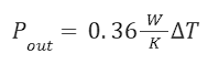
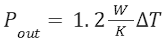
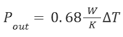
Ambient Temperature
Higher ambient temperatures reduce both the thermal margin available for temporary overloads and the heat that can be removed at the motor’s temperature limit.
If a motor starts at ambient temperature, warmer surroundings place it closer to its operating limit. In the tank analogy, the tank starts fuller. Warmer surroundings also reduce the temperature difference that drives heat transfer, restricting the outlet flow at a given stator temperature.
Together, these effects reduce the duration of temporary overloads and the force available for continuous operation.
Operation in a Vacuum
A vacuum reduces convective cooling because little or no surrounding gas is available to carry heat away. Fan cooling becomes ineffective, although heat can still leave through conduction into mounting structures and thermal radiation.
In the tank analogy, the convection outlet is largely closed while the inlet remains open wherever the motor produces force. The reduced heat removal causes temperature to rise more quickly.
Iris Dynamics does not recommend operating ORCA motors in a vacuum.
Completing the Thermal Model
Combining heat generation, heat removal, and thermal capability provides a simplified model of how the motor’s temperature changes over time:
This model treats the motor as a single effective temperature. The following comparisons use that approximation to illustrate the effects of motor size, duty cycle, and cooling.
Comparing Two ORCA™ Motors Under the Same Load
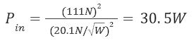
Consider an ORCA-6-24V and an ORCA-12-12V lifting and holding a 25lb weight, including the weight of the motor shaft. The load requires approximately 111 N of upward force to remain stationary. While holding the weight, neither motor performs mechanical work on the load. Both, however, continue generating winding heat.
Using the comparison values supplied in this paper, the ORCA-12-12V has:
-
Approximately 50% lower winding losses at the same holding force.
- Approximately 85% greater passive heat dissipation at the same stator-to-ambient temperature difference.
- Twice the thermal capacity.
Continuous Holding with Passive Cooling
The first comparison assumes continuous holding at an ambient temperature of 20 °C. Winding losses are calculated using the room-temperature motor constants.
|
ORCA-6-24V |
ORCA-12-12V |
|
|
Power Consumption |
|
|
|
Natural Convective Cooling |
|
|
|
Steady State temperature |
|
|
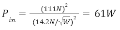
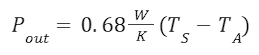
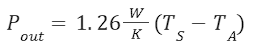
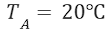
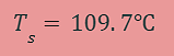
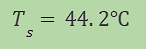
These temperatures are calculated by equating winding losses with heat removal. They do not account for the reduction in the motor constant as temperature rises and should be treated as illustrative estimates.
The comparison shows why maximum force alone is insufficient for motor selection. Although the load is within the ORCA-6-24V’s maximum force capability, the calculated equilibrium temperature indicates that it cannot sustain the load continuously under the stated passive-cooling conditions. The ORCA-12-12V reaches equilibrium at a substantially lower temperature.
Maximum Force and Speed
The difference in continuous performance becomes less apparent when comparing maximum force and speed ratings.
|
Parameter |
ORCA-6-24V |
ORCA-12-12V |
|
Maximum Force at 60 V |
426 N |
426 N |
|
Maximum Speed at 60 V |
5.3 m/s |
5.3 m/s |
These are separate maximum ratings and do not establish that maximum force and maximum speed are available simultaneously.
Despite their matching ratings in this comparison, the motors have different continuous thermal capabilities. Short-duration force requirements must therefore be assessed alongside the complete operating cycle.
Duty Cycle: Reducing Thermal Load on the ORCA-6-24V
The next comparison introduces unloaded rest periods between holding intervals. During each rest period, the weight rests on a support so the motor can release its holding force. This distinction matters: stopping movement while continuing to support the weight does not eliminate winding heating.
In the tank analogy, the inlet closes periodically while the outlet continues draining. This reduces average heat generation. See below what duty cycle would be required to achieve the same stator temperature as the ORCA-12-12V:
|
ORCA-6-24V |
ORCA-12-12V |
|
|
Power Consumption |
|
|
|
Natural Convective Cooling |
|
|
|
Duty Cycle |
|
100% |
|
Steady State temperature |
|
|
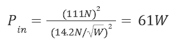
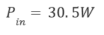
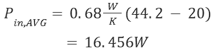
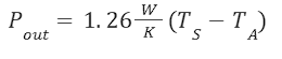
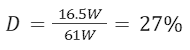
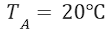
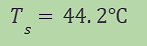
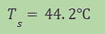
In this example, the ORCA-6-24V would require a 2.7s break for every 1s of holding time, whereas the ORCA-12-12V would attain the same stator temperature while holding the weight constantly.
Increasing Heat Removal with Forced-Air Cooling
The final comparison applies forced-air cooling to both motors while they hold the load continuously. Increased airflow improves heat removal at a given temperature difference. In the tank analogy, it opens the outlet further.
The following comparison will once more hold 25lb with 1000% duty cycle:
|
ORCA-6-24V |
ORCA-12-12V |
|
|
Power Consumption |
|
|
|
Forced Convective Cooling |
|
|
|
Steady State temperature |
|
|
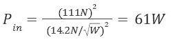
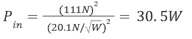


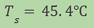
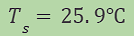
The fan cooling provides a drastic improvement to the performance of both motors, enabling this application with ease.
Final Thoughts
Maximum force defines a motor’s available force output under specified conditions. Continuous force defines the output it can sustain within its thermal limits. Selecting a motor requires both ratings to be considered alongside load duration, repetition rate, ambient temperature, and cooling.
The water-tank analogy connects the three principal thermal factors: heat generation fills the tank, thermal capacity determines how much energy can accumulate before the temperature limit is reached, and cooling drains it. Greater thermal capacity extends temporary operation; sustained operation requires heat generation and heat removal to balance.
The ORCA motor comparison illustrates why identical maximum force ratings can produce different continuous operating capabilities. Lower winding losses, greater heat dissipation, and greater thermal capacity favour sustained loading. Where continuous operation is unnecessary, unloaded rest periods can reduce average heating. Additional cooling can also extend the usable operating range.
Motor selection should therefore reflect the complete operating cycle and installation conditions, supported by thermal calculations and application-specific validation.
