
A force-feedback joystick must reproduce the intended mechanical response as its position and direction of motion change. In a multi-degree-of-freedom (multi-DoF) mechanism, this requires coordinated actuator control and an accurate relationship between actuator motion and joystick orientation.
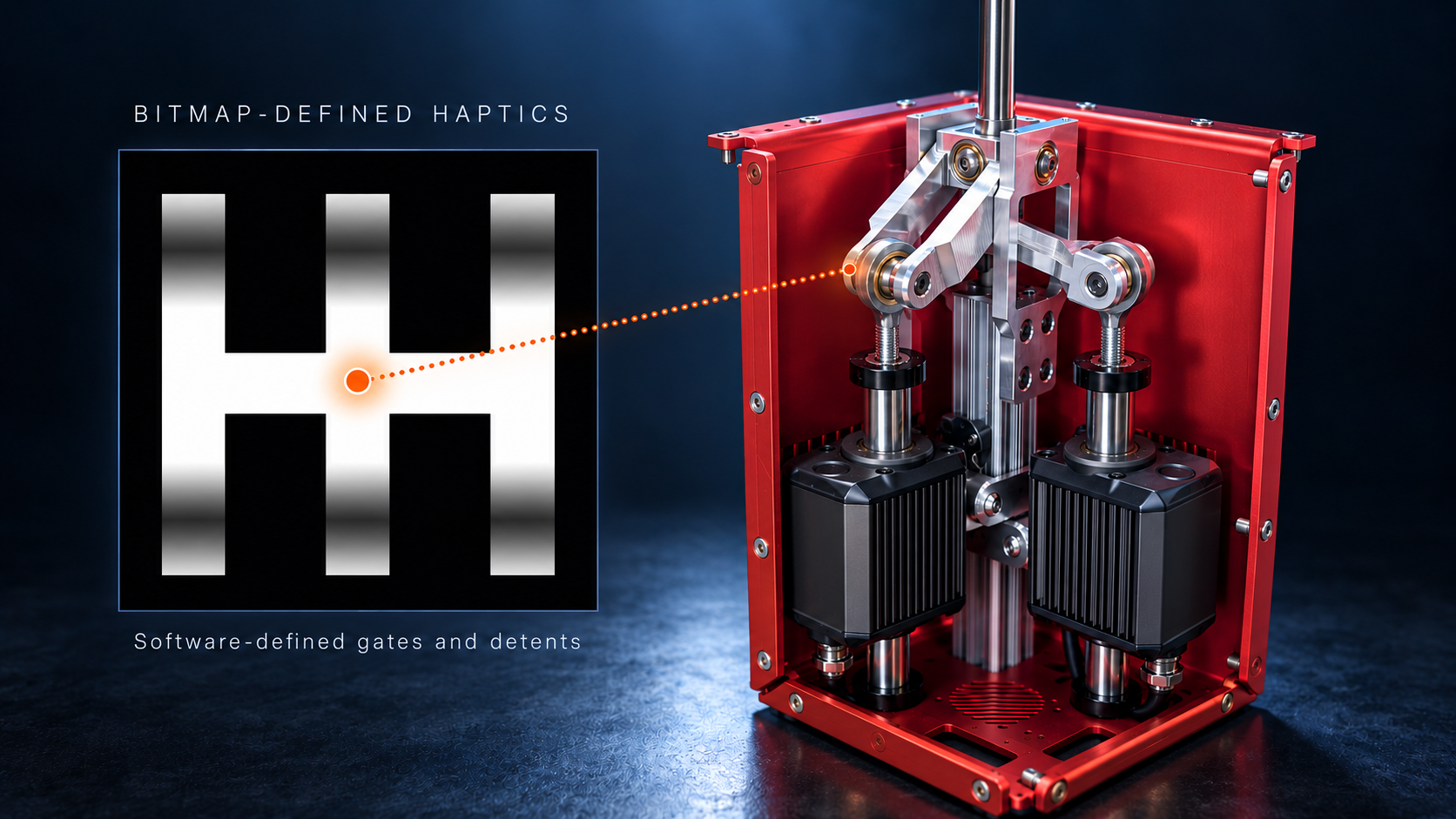
This paper examines a two-degree-of-freedom (2-DoF) joystick driven by two ORCA™ Series Smart Linear Motors. Mechanical linkages convert linear motion into pitch and roll, while kinematic models translate between actuator and joystick coordinates. A bitmap defines how the joystick responds at different positions, allowing restoring torques, virtual boundaries, and oscillation effects to be combined in software. The gearbox and maze demonstrations illustrate how these effects operate within the same mechanical assembly.
Mechanical Configuration
The joystick uses a gimbal mechanism to convert linear actuator travel into approximately ±20° of rotation. One actuator drives pitch and the other drives roll. Their linkages accommodate movement about both axes without restricting the joystick's intended range of motion.
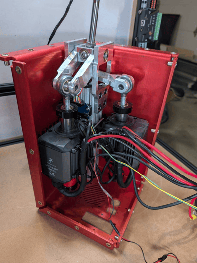 |
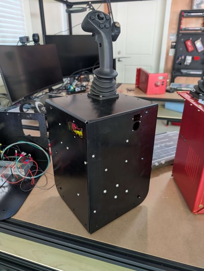
Figure 1 and 2: the assembled joystick [left] and the inner components of the joystick, including two ORCA™ motors to control pitch and roll [right]
The pitch mechanism uses a planar four-bar linkage. The frame fixes the locations of the supporting pivots, and the actuator bushings maintain the perpendicular relationship between the shaft and its support. Extending or retracting the actuator changes the linkage geometry and rotates the joystick about the pitch axis.
The roll mechanism must accommodate changes in pitch to avoid binding; changes in the pitch angle tilt the roll axis equivalently. An additional pivot linkage between the joystick shaft and roll actuator provides this freedom of movement. The fixed-length connecting rod (FG in the following figure) is rotated perpendicularly to the joystick shaft and the ORCA motor's plane of action. This enables the ORCA motor to control the roll in a different plane from that of the motor itself.
Figure 3 and 4: Pitch mechanism renderings [left] and tilted mechanism and roll linkage [right]
Position Tracking and Effect Modelling
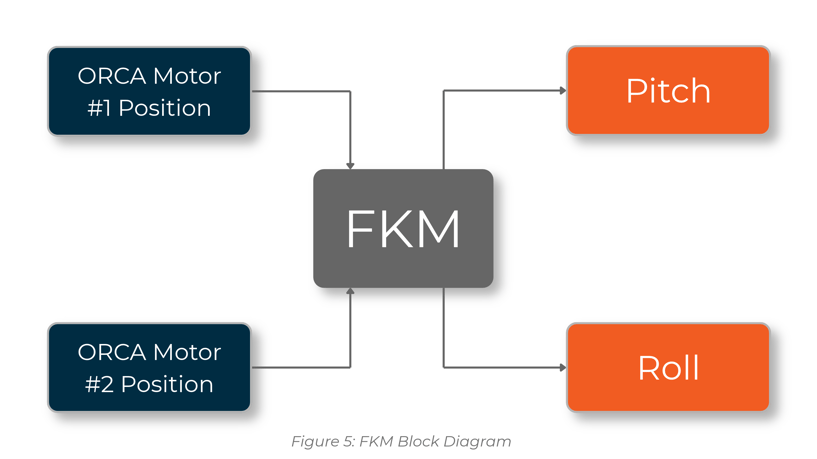
Each ORCA motor measures its linear displacement. The forward kinematic model (FKM) converts these measurements into joystick pitch and roll, establishing the position at which the haptic model is evaluated.
|
The model uses a two-dimensional bitmap to define effects across the operating range. Pixel locations correspond to pitch and roll coordinates, while pixel values specify the response at each location. Gradients define restoring torque profiles, black regions identify virtual boundaries, and additional colour channels can control oscillations. This representation allows several effects to be combined and modified without changing the mechanical assembly. |
|
| Figure 6: Pitch-roll position plot using a green marker as the calculated joystick position |
|
Restoring Torque and Differential Stiffness
A centring spring returns a joystick towards its neutral position by applying a restoring torque. Figure 7: Restoring-force plots
 Figure 8: Greyscale gradient bitmap |
In the bitmap model, the local image gradient defines the direction and magnitude of this torque. Changing the gradient changes the responses across the operating range, allowing resistance to vary with position and direction. Stiffness describes how restoring torque changes with angular displacement. The shape of the torque profile therefore determines the local stiffness. Adjusting that profile allows the joystick to reproduce different responses along the two axes or within selected regions, including centring behaviour and detents. |
Software Dead Stops
Software dead stops create resistance a defined boundaries within the joystick's operating range. Black regions in the bitmap identify these boundaries, including the outer perimeter and any internal barriers.
Oscillation Effects
ORCA motor controllers include configurable oscillation effects that can reproduce rumble, clicks, and vibration-based alerts. These effects can be assigned to specific regions through additional bitmap colour channels.
As the joystick moves, the controller reads the values at its current position and updates the motor's oscillation settings. A selected region can therefore produce a distinct vibration response while retaining the restoring torques and virtual boundaries defined elsewhere in the map.
Converting Haptic Effects into Motor Commands
The haptic model defines the required response in joystick coordinates, but the actuators apply linear forces. Converting the requested pitch and roll torques into motor commands requires the controller to account for the leverage of the mechanisms at its current orientation. Running most of these haptic effects directly on the motor allows a much higher control speed.
For an axis represented by a single effective lever arm, the required actuator force is the requested torque divided by that lever arm. Because leverage changes as the joystick moves, the controller recalculates this relationship throughout the operating range. The force conversion must also account for any interaction between the axes.
The complete control cycle links position tracking, effect modelling, and motor command generation. The FKM establishes joystick orientation from actuator measurements. The controller then evaluates the bitmap, converts the required torques into actuator forces, and uses the IKM to determine any software stop positions. The resulting force, stop, and oscillation commands are sent to the motors.
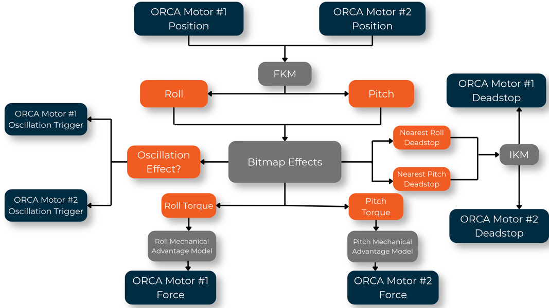
Figure 10: Joystick command flow chart
Consistent communication timing is necessary to preserve the intended response. Delays or mismatched updates are particularly apparent at stiff boundaries, where small position changes can require rapid changes in actuator force.
Application Demonstrations
|
Figure 11: Gear-selector bitmap |

Six-Speed Gear Selector
A six-speed gear selector (figure 10) combines software dead stops with restoring torque profiles. Black regions define the shift gates and constrain movement to the permitted paths. Gradients create detents at the gear positions, providing a distinct response as the joystick reaches each location.
Haptic Maze
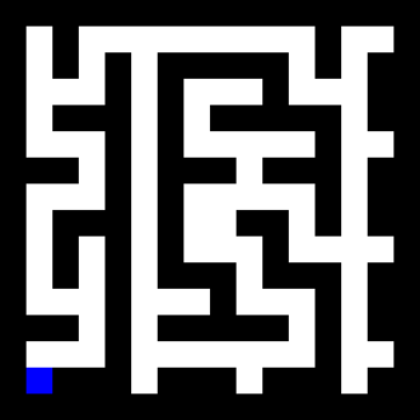
The maze demonstration (figure 11) uses software dead stops to define passage boundaries. A blue region marks the finish and activates an oscillation effect when the joystick enters it. The same bitmap therefore controls both the physical resistance encountered along the route and the feedback that indicates completion.
Application use Cases
The joystick demonstrations show how one mechanism can provide several different mechanical behaviours through software. The same principles can be applied to other systems where the resistance, movement constraints, or feedback need to change during operation.
Simulation and Training - Flight Controls
Aircraft controls change in feel depending on flight conditions. In a flight simulator, haptic control can vary the resistance of the control stick with simulated airspeed, shift its centre position to represent trim, and introduce vibrations to indicate events such as an approaching stall. These effects allow the same mechanism to reproduce different aircraft behaviours and training scenarios through software.
Remote Equipment Control
When operating an inspection robot remotely, the operator often relies on cameras to understand how it is interacting with its surroundings. A force-feedback joystick could increase resistance as the robot's manipulator encounters a load, or generate a vibration when a tool makes contact. This provides physical feedback to help the operator judge contact and adjust their commands when the camera view is limited.
Configurable Machine Controls - Garbage Trucks
A garbage truck may use a joystick to control several functions, such as positioning a collection arm, gripping a bin, and lifting it into the hopper. Each function benefits from a different control arrangement. Software-defined constraints could allow movement across both axes when positioning the arm, then guide movement along a single axis during lifting. Detents and vibrations could indicate selected modes or completion of a movement, helping the operator identify what the controls are doing by feel.
Guided Movement and Training - Excavators
Operating an excavator requires coordinated movements of the boom, stick, and bucket. In a training simulator, a haptic joystick could guide the operator through the control inputs needed to perform a particular movement, such as maintaining a level bucket path. Resistance could increase when the operator moves away from the intended inputs, while assistance could help demonstrate the correct sequence. The level of guidance could then be reduced as the operator becomes more familiar with the controls.
Final Thoughts
The two-actuator joystick demonstrates how kinematic modelling and bitmap-based control can combine differential stiffness, virtual boundaries, and oscillation effects across pitch and roll. Different complex mechanical responses can be defined through image generation while retaining the same actuators, linkages, and control hierarchy.
The fidelity of these effects depends on accurate coordinate and force transformations, compensation for changing leverage, and coordinated actuator updates. These requirements become more demanding as virtual stiffness increases or boundaries require simultaneous changes along both axes. The same control principles can be applied to systems with additional degrees of freedom, provided that their kinematic model and effect representations account for the added motion.
